Rigidity, aesthetics, and weight are at the top of the list of factors that engineers at the OEM level must consider when deciding between round or nonround tubing for design projects. Conversely, formability, weldability, and repeatability are the primary concerns of fabricators.
With recent advancements in production methods, equipment, tooling, and bending knowledge among fabricators and their customers, the use of square and rectangular tubing is increasing. Nonround tubing has a growing presence in structural and mechanical applications in industries too numerous to count.
Quality Requirements
Formability of the material, specifically bendability, is a critical factor in tube fabricating. To fully assess bending feasibility and determine the optimal method, the fabricator must know the full scope of the bend constraints. For example, is a depression or wrinkling on the inside of the bend acceptable? How about the outside of the bend? Is a depression along the outside of the bend permissible? Both of these examples are typical deformations that commonly occur when bending square or rectangular tubing.
Applications that allow some deformation in the bend area are the most favorable because they allow the fabricator to consider the largest variety of bending methods. In other words, when the application has some latitude in the type and severity of deformations, the fabricator doesn’t have to spend too much time dwelling on his ability to deliver good parts, but can go quickly from planning to production. However, bending a part that has strict quality constraints related to the tube’s cross section in the bend region narrows the process choices. When dealing with the most stringent requirements, a rotary draw tube bender equipped with a mandrel often is the only way to go, because this method controls the material flow completely.
However, this doesn’t mean that the machine will produce good parts the first time or every time.
Tip the Scales of Success
To put things into perspective, nonround tubing is subject to the same mechanical forces during bending as round tubing. Material on the outside region of the bend area (extrados) stretches as the tube is bent, while material at the inside region (intrados) compresses as the tube is bent. Material near the central region of the tube (neutral axis) is neither compressed nor stretched. When compared to the same size round tube, nonround tubing has a greater amount of material present on both the extrados and intrados regions of the bend, making it more difficult to control the effects of material flow. Additionally, the four corners, which by their nature are resistant to forming, require a greater amount of force to initiate the bending process.
For these reasons, a machine with a little extra bending capacity is recommended. One inch diameter of extra capacity should do the trick. For example, if the longest side of the tube is 3 in., the bending machine should rated to bend 4-in. round tube. This guideline holds regardless of bending orientation; whether the bend is along the major plane (hard way) or minor plane (easy way), the guideline is valid. This rule of thumb helps to ensure that the bending machine can produce enough torque to make the desired bends without stalling.
When all other factors are equal, a bend with a short inside bend radius (ISR) is more challenging than one with a long ISR. It is best to keep the ISR, which is measured from the center of the bend to the inside of the tube bend, to at least 1 ½ times the tube diameter based on the plane on which it is being bent (see Figure 1). For example, a rectangular tube measuring 2 by 3 in., bent the easy way, should be bent on a machine rated for 4-in. tube. The ISR should be a minimum of 3 in. If the same tube were to be bent the hard-way, the minimum ISR would be 4.5 in.
Material selection also plays a substantial role in bending success. Material elongation is the key mechanical property. Elongation should be at least 20 percent; if it is less than that, consider negotiating (persistently, if necessary) to substitute a more formable material. After all, this could be the difference between an acceptable bend and a reject.
Optimal Tooling
The next step in the process is to determine the optimal tooling requirements. Requesting a quotation from a reputable and experienced rotary draw tube bending tool supplier is usually the best option for an accurate assessment of the required clamp length, mandrel and wiper (mainly the dimensions, materials, and surface finish), and of course cost and lead time.
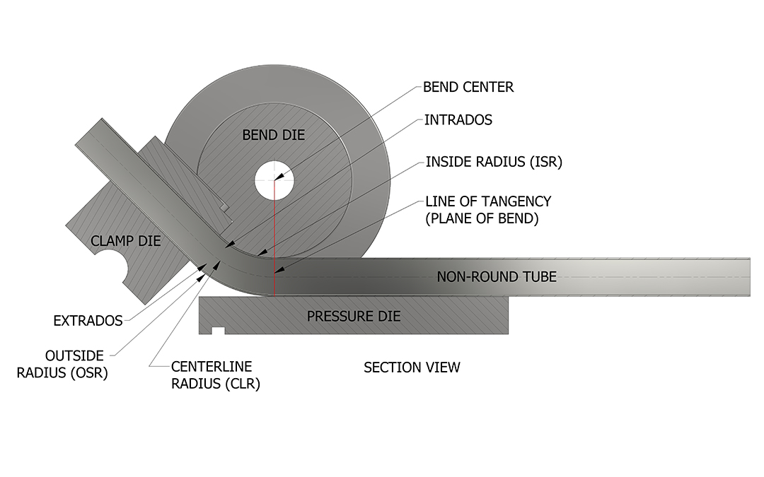
Figure 1
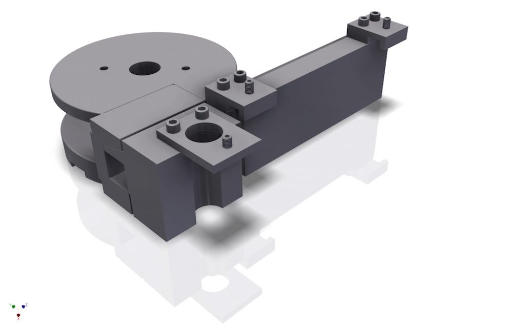
Unlike round tooling, which comprises two halves that meet in the middle of the tube, tooling for squares and rectangles requires a different tube cavity design to deal with tube corners that expand outward toward the tooling cavity corners. Unless a portion of the bend die cavity is relieved, the tubing is difficult to remove from the bend die. The most effective non-round tooling features a tapered-leaf design that eliminates the need for a split-die actuator (a mechanical device that separates the top portion of the bend die from the tube) to prevent the tube from seizing in the tooling (see Lead Image). Once the tapered-leaf clamp and pressure die open, the tube is free and clear to move to the next plane-of-bend or to be removed from the bender. Furthermore, the tapered-leaf design helps to maintain vertical force against the upper and lower tube faces, which offers optimal containment on all four sides of the tube.
Proceed with Confidence
Covering all the bases boosts confidence in any project. For a non-round tube bending application, the five steps to remember are:
- Find out the quality considerations.
- Make sure the machine has the power to make the bend.
- Review the bend radius to be sure it isn’t too small.
- Make sure the material is suited for forming, not machining.
- Find out the optimal tooling requirements for the application.
This will eliminate surprises and increase the odds for success.